Silicon Controlled Rectifier
Silicon Controlled Rectifier (SCR)
Silicon Controlled Rectifier (SCR), also known as thyristor, is a high-power electrical component. It has the advantages of small size, high efficiency, and long service life. In automatic control systems, it can be used as a high-power driver to control high-power devices with low-power controls. It has been widely used in AC and DC motor speed control systems, power regulation systems, and servo systems.
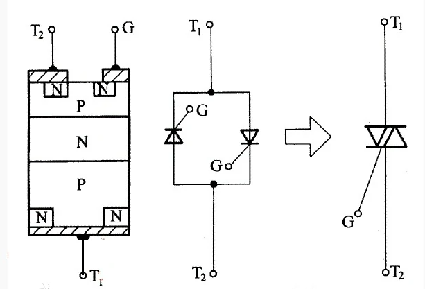
There are two types of thyristor: unidirectional thyristor and bidirectional thyristor. Bidirectional thyristor, also known as three-terminal bidirectional thyristor, abbreviated as TRIAC. Bidirectional thyristor is structurally equivalent to two unidirectional thyristors connected in reverse, and this type of thyristor has bidirectional conduction function. Its on/off state is determined by the control pole G. Adding a positive (or negative) pulse to the control pole G can make it conduct in the forward (or reverse) direction. The advantage of this device is that the control circuit is simple and there is no reverse voltage withstand problem, so it is particularly suitable for use as an AC contactless switch.
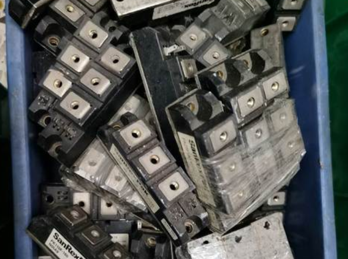
1 SCR structure
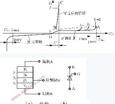
We are using unidirectional thyristors, also known as ordinary thyristors. They are composed of four layers of semiconductor material, with three PN junctions and three external electrodes [Figure 2 (a)]: the electrode led out of the first layer of P-type semiconductor is called anode A, the electrode led out of the third layer of P-type semiconductor is called control electrode G, and the electrode led out of the fourth layer of N-type semiconductor is called cathode K. From the Electronic symbol of the thyristor [Fig. 2 (b)], we can see that it is a unidirectional conductive device like the diode. The key is to add a control electrode G, which makes it have completely different operating characteristics from the diode.
The P1N1P2N2 four layer three terminal device, based on silicon single crystal as the basic material, began in 1957. Due to its characteristics similar to vacuum thyristors, it is commonly referred to internationally as silicon thyristors, abbreviated as thyristors T. Additionally, because thyristors were originally used in static rectification, they are also known as silicon controlled rectifier elements, abbreviated as thyristor SCR.
In terms of performance, silicon controlled rectifier not only has single conductivity, but also has more valuable controllability than silicon rectifier components (commonly known as "dead silicon"). It only has two states: on and off.
Thyristor can control high-power electromechanical equipment with milliampere level current. If this power is exceeded, the average current allowed to pass through will decrease due to a significant increase in component switching loss. At this time, the nominal current should be downgraded for use.
There are many advantages of thyristor, such as controlling high power with low power, and the power amplification factor can reach several hundred thousand times; Extremely fast response, turning on and off within microseconds; No contact operation, no sparks, no noise; High efficiency, low cost, etc.
Thyristors are mainly classified in terms of appearance as bolt shaped, flat plate shaped, and flat bottom shaped.
Structure of thyristor components
Regardless of the appearance of the thyristor, their core is a four layer P1N1P2N2 structure composed of P-type silicon and N-type silicon. See Figure 1. It has three PN junctions (J1, J2, J3), with anode A introduced from the P1 layer of the J1 structure, cathode K introduced from the N2 layer, and control electrode G introduced from the P2 layer. Therefore, it is a four layer, three terminal semiconductor device.
2 operational principle
Structural elements
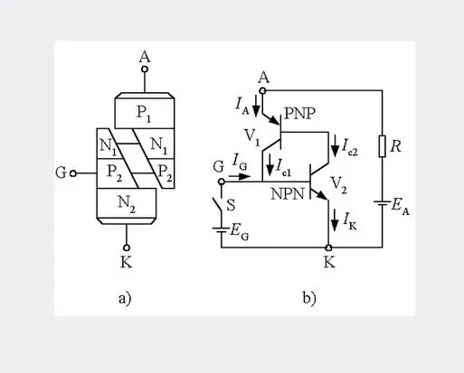
Thyristor is a P1N1P2N2 four layer three terminal structural element with three PN junctions. When analyzing the principle, it can be regarded as composed of a PNP transistor and an NPN transistor, and its equivalent diagram is shown in the right figure. Bidirectional thyristor: Bidirectional thyristor is a silicon controlled rectifier device, also known as TRIAC. This device can achieve contactless control of AC power in circuits, controlling large currents with small currents. It has the advantages of no sparks, fast action, long service life, high reliability, and simplified circuit structure. From the appearance, bidirectional thyristor is very similar to ordinary thyristor, with three electrodes. However, except for one electrode G, which is still called the control electrode, the other two electrodes are usually no longer called the anode and cathode, but collectively referred to as the main electrodes Tl and T2. Its symbol is also different from that of ordinary thyristors, which is drawn by reversing the connection of two thyristors together, as shown in Figure 2. Its model is generally represented by "3CTS" or "KS" in China; Foreign data can also be represented by 'TRIAC'. The specifications, models, appearance, and electrode pin arrangement of bidirectional thyristor vary depending on the manufacturer, but most of its electrode pins are arranged from left to right in the order of T1, T2, and G (when observed, the electrode pins are facing downwards and facing the side marked with characters). The appearance and electrode pin arrangement of the most common plastic encapsulated structure bidirectional thyristor in the market are shown in Figure 1.
3 SCR Characteristics
In order to intuitively understand the working characteristics of thyristors, let's take a look at this teaching board (Figure 3). The thyristor VS is connected in series with the small light bulb EL and connected to the DC power supply through switch S. Note that anode A is connected to the positive pole of the power supply, cathode K is connected to the negative pole of the power supply, and control electrode G is connected to the positive pole of the 1.5V DC power supply through button switch SB (here, KP1 type thyristors are used, and if KP5 type thyristors are used, they should be connected to the positive pole of the 3V DC power supply). The connection method between the thyristor and the power supply is called forward connection, which means that the positive voltage is applied to both the anode and control poles of the thyristor. Turn on the power switch S, but the small light bulb does not light up, indicating that the thyristor is not conducting; Press the button switch SB again to input a triggering voltage to the control pole. The small light bulb lights up, indicating that the thyristor is conducting. What inspiration did this demonstration experiment give us?
This experiment tells us that to make the thyristor conductive, one is to apply a forward voltage between its anode A and cathode K, and the other is to input a forward trigger voltage between its control electrode G and cathode K. After the thyristor is turned on, release the button switch, remove the triggering voltage, and still maintain the conduction state.
4 Characteristics of SCR
At a touch. However, if a reverse voltage is applied to the anode or control electrode, the thyristor cannot conduct. The function of the control pole is to turn on the thyristor by applying a forward trigger pulse, but it cannot be turned off. So, what method can be used to turn off the conducting thyristor? By turning off the conducting thyristor, the anode power supply (switch S in Figure 3) can be disconnected or the anode current can be reduced to the minimum value required to maintain continuity (referred to as the maintenance current). If there is an AC voltage or pulsating DC voltage applied between the anode and cathode of the thyristor, the thyristor will automatically turn off when the voltage crosses zero.
Application Type
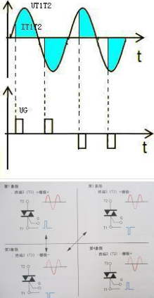
Figure 4 shows the characteristic curve of bidirectional thyristor.
As shown in the figure, the characteristic curve of bidirectional thyristor is composed of curves within the first and third quadrants. The curve in the first quadrant indicates that when the voltage applied to the main electrode causes Tc to have a positive polarity towards T1, it is called the forward voltage and represented by the symbol U21. When this voltage gradually increases to the turning point voltage UBO, the thyristor on the left side of Figure 3 (b) triggers conduction, and the on state current at this time is I21, flowing from T2 to Tl. From the figure, it can be seen that the larger the triggering current, the lower the turning voltage. This situation is consistent with the triggering conduction law of ordinary thyristor. When the voltage applied to the main electrode causes Tl to have a positive polarity towards T2, it is called a reverse voltage and is represented by the symbol U12. When this voltage reaches the turning point voltage value, the thyristor on the right side of Figure 3 (b) triggers conduction, and the current at this time is I12, with a direction from T1 to T2. At this point, the characteristic curve of the bidirectional thyristor is shown in the third quadrant of Figure 4.
Four triggering methods
Due to the fact that on the main electrode of the bidirectional thyristor, it can be triggered and conducted regardless of whether a forward or reverse voltage is applied, and whether the trigger signal is forward or reverse, it has the following four triggering methods: (1) When the voltage applied by the main electrode T2 to Tl is a forward voltage, the voltage applied by the control electrode G to the first electrode Tl is also a forward trigger signal (Figure 5a). After the bidirectional thyristor triggers conduction, the direction of current I2l flows from T2 to T1. From the characteristic curve, it can be seen that the conduction law of the bidirectional thyristor trigger is carried out according to the characteristics of the second quadrant, and because the trigger signal is in the forward direction, this trigger is called the "first quadrant forward trigger" or the I+trigger method. (2) If the forward voltage is still applied to the main electrode T2 and the trigger signal is changed to a reverse signal (Figure 5b), then after the bidirectional thyristor triggers conduction, the direction of the on state current is still from T2 to T1. We call this trigger the "first quadrant negative trigger" or the I-trigger method. (3) Two main electrodes are applied with a reverse voltage U12 (Figure 5c), and a forward trigger signal is input. After the bidirectional thyristor is turned on, the on state current flows from T1 to T2. The bidirectional thyristor operates according to the third quadrant characteristic curve, so this trigger is called the III+trigger method. (4) The two main electrodes still apply reverse voltage U12, and the input is a reverse trigger signal (Figure 5d). After the bidirectional thyristor is turned on, the on state current still flows from T1 to T2. This trigger is called III touch
(4) The two main electrodes still apply reverse voltage U12, and the input is a reverse trigger signal (Figure 5d). After the bidirectional thyristor is turned on, the on state current still flows from T1 to T2. This trigger is called the III trigger method. Although bidirectional thyristor has the above four triggering methods, the triggering voltage and current required for negative signal triggering are relatively small. The work is relatively reliable, so negative triggering methods are widely used in practical use.
5 Purpose
The most basic use of ordinary thyristors is controllable rectification. The familiar diode rectifier circuit belongs to an uncontrollable rectifier circuit. If the diode is replaced with a thyristor, a controllable rectifier circuit can be formed. Taking the simplest single-phase half wave controllable rectifier circuit as an example, during the positive half cycle of the sinusoidal AC voltage U2, if the control pole of VS does not input the trigger pulse Ug, VS still cannot conduct. Only when U2 is in the positive half cycle and the trigger pulse Ug is applied to the control pole, the thyristor is triggered to conduct. Draw its waveforms (c) and (d), and only when the trigger pulse Ug arrives, will there be voltage UL output on the load RL. Ug arrives early, and the thyristor conduction time is early; Ug arrived late, and the thyristor conduction time was later. By changing the time when the trigger pulse Ug arrives at the control pole, the average output voltage UL on the load can be adjusted. In electrical technology, the half cycle of alternating current is often set at 180 °, known as the electrical angle. In this way, the electrical angle experienced during each positive half cycle of U2 from zero to the moment the trigger pulse arrives is called the control angle α; The electrical angle at which the thyristor conducts within each positive half cycle is called the conduction angle θ。 Obviously, α and θ Both are used to represent the conduction or blocking range of thyristors during half a cycle of withstanding forward voltage. By changing the control angle α Or conduction angle θ, By changing the average value UL of the pulse DC voltage on the load, controllable rectification is achieved.
1: Low power plastic encapsulated bidirectional silicon controlled rectifier is commonly used as an acoustooptic lighting system. Rated current: IA is less than 2A.
2: Big; Medium power plastic sealed and iron sealed thyristors are commonly used as power type controllable voltage regulating circuits. Like adjustable voltage output DC power supply, etc.
3: High power high-frequency thyristor is commonly used in industry; High frequency melting furnace, etc
